Setting up Visual Studio Code IDE on Ubuntu 22.04 for Marlin

I needed to do this help a friend debug a problem he had with Marlin code. Normally I try and avoid IDE’s other than Eclipse but in this case there does not seem a great deal of integration for Eclipse with Marlin and it was more important to get bug chasing

I cam across a number of poorly documented hurdles getting this set up for Marlin (2.1). Depending on how long it is since this got published then some/all of these issues may have gone away.

Download Visual Studio Code. You need the deb package. From here: https://code.visualstudio.com/download

Once downloaded you can easily install the thing on 22.04 by right clicking on the download deb file and then select “Open with other application” then select “Software Install” and you are away.

Alternatively, you can do this on the command line with:

sudo apt install ~/Downloads/filename.deb 

You should end up with an icon in your Programming dropdown from the Applications menu top left of the Gnome desktop. The icon you need to click is obviously Visual Studio Code.

Open you newly installed Visual Studio Code IDE. Click on the extensions icon in the left hand column. It looks like four boxes.
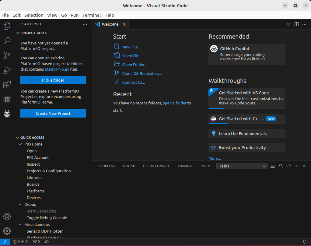
Microsft Visual Studio Code after installation
The first view of VSC

Then in the search box type in “Auto Build Marlin” Install it.

You will end up with two new icons on the left hand side. One “M” is Marlin auto build.
The one that looks like an alien is actually not yet installed. That’s next. It’s called Platformio. It needs Python. But unfortunately it wont recognise the default Python3 in Ubuntu 22.04. So we have some kerfuffling to do with Python before we can install it. But first close down Visual Studio Code.

Python

If you open a console and type “which python” the system wont find it. That is because on 22.04 you have python3. Type “which python3” and all is well. But that does not help us with Platformio.

If you open Visual Studio Code and try installing Platform IO by clicking the alien icon. It will fail with:

PlatformIO: Can not find working Python 3.6+ Interpreter. Please install the latest Python 3 and restart VSCode.

There were two things I tried to get this working. The first may be redundant or it may be necessary to have along with the second. Either way I only got PlatformIO to install after I had done the second of these.

Close down Visual Studio Code.

The first “fix” was to install this which sorts out an alias for Python3 so it can be invoked with “Python” as well as Python3

sudo apt install python-is-python3

This though still failed with installing PlatformIO. For me it it failed with the same error message. Though now the system could access the Python interpreter as “python” as well as “python3”

This was the bit I added next and was needed to be installed before Platform IO would then itself install.

sudo apt install -y python3-venv

So what is python3-venv? It appears to be a way of creating a multiple of virtual Python environments so keeping, I think, each Python program running with its own clone of the interpreter. But whatever – that solved the problem.

When you’ve done these two installs restart Visual Studio Code and then click on the aliens head. Platform IO should install.

Now we need to set up our MARLIN code

Download it from here… https://marlinfw.org/meta/download/
The latest version for me was a bugfix level but normally I’d go for a stable level.

Unpack the downloaded zip file somewhere you want it.

Then in VSC click on the Aliens head aka open PlatformIO. It will do some initialising in the left hand column then it’ll look like this.

Click on “Pick a Folder” and point it at your Marlin code you just unzipped.
Then Platform IO will start configuring the project. There’s also, for me, an opportunity to install “Dev Containers” from Microsoft. I waited until the PlatformIO had completed configuring the project then took my life in my hand and installed the “Dev containers”. It installed and I then closed the resulting window on it. Leaving me with this…
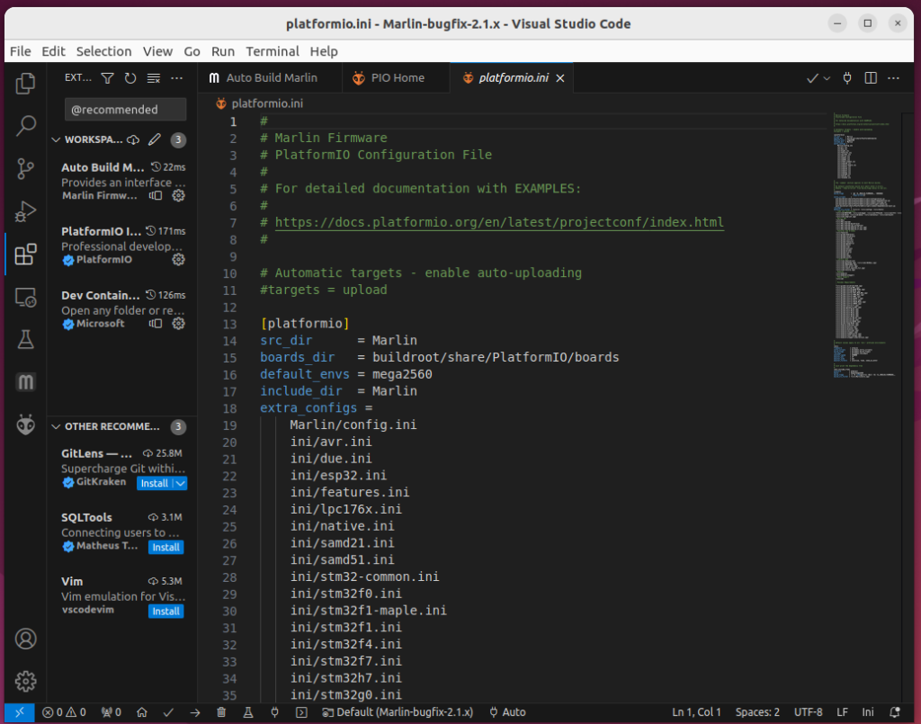
visual studion code with Marlin
Visual Studio Code ready to debug Marlin

Of course we will need to modify the config files etc in the code. But first just to make sure the whole thing works go to “AutoBuild” and click build for one of the default environments.
It built this is what I get.

At the end, if successful, it opens the newly created directory holding the new files including the “firmware.hex”.
Fixing Pronterface on Ubuntu 22.04

There’s some bad news for those installing Printrun (which includes Pronterface) from the repository for Ubuntu 22.04. It doesn’t work. But there is a way of fixing Pronterface on Ubuntu 22.04.

But sadly, if you install Pronterface (aka the Printrun package) using Synaptic Package Manager or the ritual…

sudo apt update
sudo apt install printrun

You may (probably will) find that Pronterface won’t work. (But salvation is at hand!)

i.e. By “won’t work” I mean it never comes up. It crashes. Even if you try running it from a terminal you will get no further.

I believe this is associated with a missing/redundant library that got dropped from 22.04 that Pronterface (and the other utilities in Printrun) have some horrible dependency on.

I originally thought that the problem only occurred if your 22.04 was an upgrade from 20.04. But today I proved that wrong when a clean install of Ubuntu 22.04 installed Printrun and it also crashed. As Printrun is more-or-less an abandoned Ubuntu package there is no realistic chance that this package issue will be fixed soon. If ever (I hope I’m wrong but…)

But! Still, there is a way of fixing Pronterface!

First uninstall all the duff Printrun files either with Synaptic or with a terminal and…

sudo apt-get remove Printrun -y

All is not lost because the guy who developed the package has made available a git package which can be used instead. We are not actually fixing the Ubuntu Pronterface package, we are installing an updated version from Git. Package -wise it’s is not as clean as using an installed package, but if like me you are really more interested in getting the job done than faffing about then it is way beyond good enough.

Fixing Pronterface with Git

It can be done other ways but the easiest way is to use Git. Git is described here: https://git-scm.com/

If you don’t have Git installed it’s easy as there is a (working) Ubuntu package. Do the ritual..

sudo apt update
sudo apt install git

Then create a directory into which you are going to put the working code. For me it’s Mine it’s…

mkdir /home/chalkie/pronterface-git

Navigate from a terminal into that directory. We are going to download a Printrun Git package from: https://github.com/kliment/Printrun

 git clone https://github.com/kliment/Printrun

When it’s done you can start Pronterface from the command line with…

/home/chalkie/pronterface-git/Printrun/pronterface.py

And it should all work as normal from there on in.

Adding a Launcher for Pronerface to the Main Menu

But, of course that’s all rather ugly running it from the command line so add it to the main menu.

Go to the top left of the desktop and open Applications->System Tools->Prefences->Main Menu

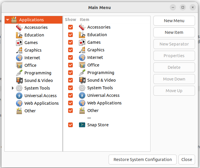
You’ll get something like this.

Image Main Menu window Ubuntu 22.04

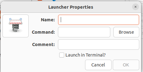
Go into the menu item where you want to have Pronterface (for me its Programming) Then click the “New Item” button. You get this.

Launcher Properties Dialog Ubuntu 22.04

In the Name field put whatever you like for me it’s Pronterface-git.

The Command field needs the path to the copy of pronterface.py we’ve just installed.

Add whatever you like in the Comment field.

Then click the spring launcher icon on the left and add the path to the icon you want to use. Aka

/home/chalkie/pronterface-git/Printrun/pronterface.ico

click OK and you are done. You’re shiny new fixed pronterface should now run as normal when you click the icon in the Applications menu. That’s how I went about fixing Pronterface on Ubuntu 22.04. I works for me. I hope it works for you too.

My other 3D printer posts can be found Here

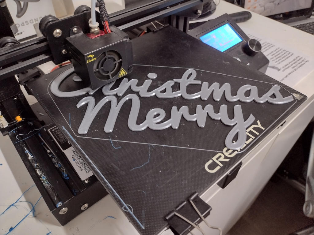
A Merry Christmas on an Ender 3

As it’s nearing Christmas I thought I’d print a 3D “Merry Christmas” banner on my Ender 3 so it could then be stuck to my/your gate/house/fence/door or whatever. I’ve been meaning to add a few Ender 3 projects here for some time. This first one is a nice simple example. Maybe someone will find it useful too. The STL and Gcode files are below in a zip.

Here’s the final result.

Photographed on the black glass of our hob (which obviously was turned off!)

Simply two words. “Merry” and “Christmas”. I used the biggest font I could while still fitting both words onto the Ender 3 build plate. It actually prints the “Merry” below “Christmas” but as they are separate words that doesn’t matter.

A Cursive Font

The font I used was PacificoRegular and you can find this font Here on Google Fonts. It’s a nice cursive font for giving the look of joined up writing. For obvious reasons this makes mounting the whole word on a wall or gate much, much easier.

Size and Time Taken

The “Christmas” is approximately 11inches (28cms) long and 3 inches (8cm) high and the “Merry” is 7.5 inches (19cm) long and also 3 inches (8cm) high. The words are 2mm thick.

Printing this “Merry Christmas” on an Ender3 took 2hr 37 m.

Here she is on the build plate caught en-flagrant so to speak. (I discarded the dot on the “i” as it was not joined to the rest of “Christmas”.)

Ender 3 printing Merry Christmas
Yes – It reads “Christmas Merry” but I’ll leave you to rearrange as you wish after printing. (they are separate!)
I really must tidy up before taking these images in future!

I’ve included a Zip file (below) to two STL files. (One for “Merry” the other “Christmas”), and the Gcode file that I used to print them both on my Ender 3, so if you have an Ender 3 then you should be able to just use the Gcode file straight out of the zip. You <may> need to build a new one with a slicer from the STL files if you are using a different 3D printer.

Anyway, Merry Christmas!

Mirror a Design in Freecad

I wanted to create a separate 3D print that was the mirror image of one I had already had. So I needed to mirror a design in Freecad. There is probably a better way of doing this but I haven’t found it yet.

This is not about simply mirroring a single object but mirroring a completed design. By mirroring I mean making an inverse copy, like a mold from a die or in my case the left hand end of a symmetric object from a design for the other half or one end.

Background

I had a design which was a seat in two halves that I wants to 3-D print on my Ender 3. The two halves plug into each other. One was the left side and one the right. They are in essence the same part but one with a socket and the other a plug. But of course other than the socket and plug they are exactly the same – but mirrored.

So rather than design the thing twice I copied the plug end then changed the plug to a socket. The only problem then was that they were both right handed. One of them needed to be mirrored to become the left hand end. So I needed to mirror the design in Freecad.

This it what I did

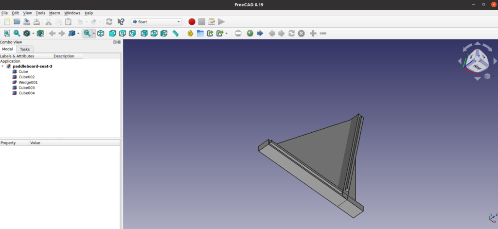
Here’s the part ….

Here’s the part

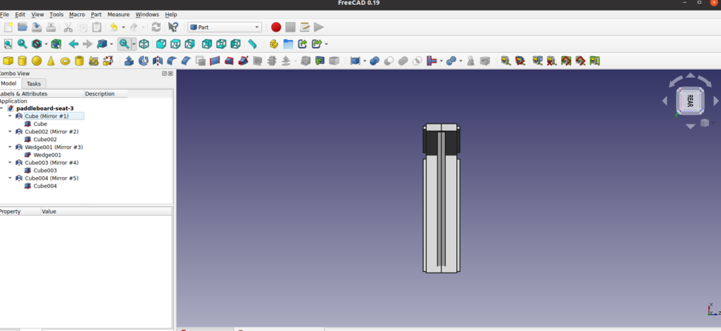
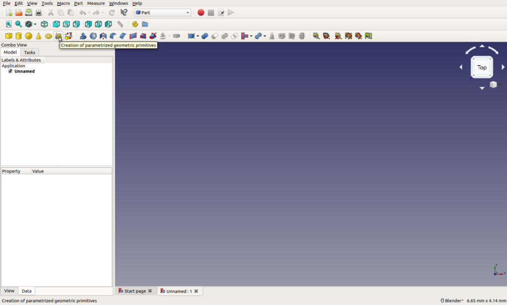
Go to Part design in the menu. Select all of the parts of the design (i.e. use ctrl mouse-click to select each part) Then in the part menu select mirroring… . This will build you an exact mirror of the original.

So far so good.

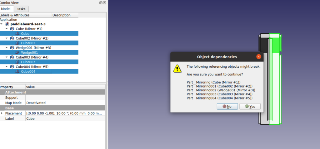
The problem is is that the original is still there and the parts in the original are used to build the mirrored design which means you cannot delete them without risking breaking the design.

Like this…

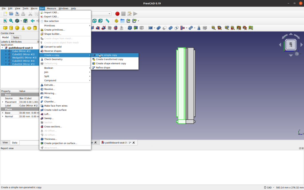
The trick is that after the mirroring stage, before you delete anything, you select the mirrored items then under “create a copy” in the Part menu, select “create a simple copy”.

This does exactly as it says. It duplicates the items you have selected BUT the new items will not be dependent on the original. Now you can select the originals and the first mirrored copy and delete them. Leaving the simple copy as the finished inverted item!

As I said I expect there is a better way without needing the two step process but I am darned if I can find it. The rest of my Freecad posts are Here

Ender 3 Leveling the Bed

Here’s how I go about leveling the bed on my Ender 3. I do it by a mixture of eye, feel and repetition. I expect most folk use a similar process but here it is anyway. There are some great gizmo’s you can use instead that take most of the grief and suffering out of it but I’ll come to those later. I still use the manual process.

But if you want to just go straight to the gizmo’s here they are on Amazon. For 8 bit machines (and I assume 32 bit as well) there’s this BL Touch on Amazon. If you have a 32 bit board then you can use the more sophisticated CR Touch here on Amazon. If you can’t figure out if your Ender 3 is 8 bit or 32 bit then maybe this This Post or This Post will help. (there is another one as well that deals specifically with the CR Touch and the 32 bit processor issue in This Post).

Leveling the Bed: This is What I do.

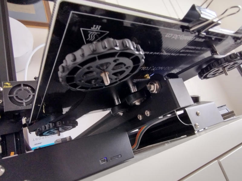
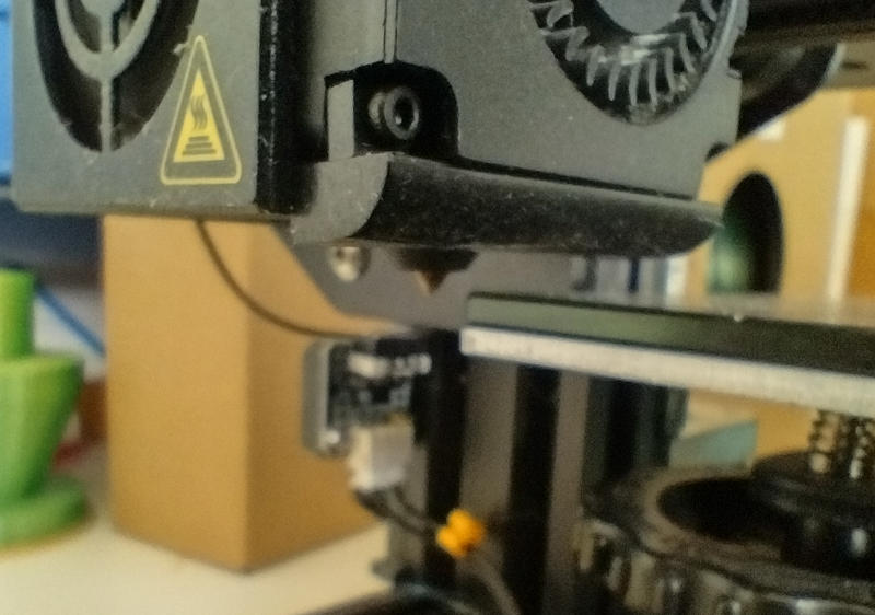
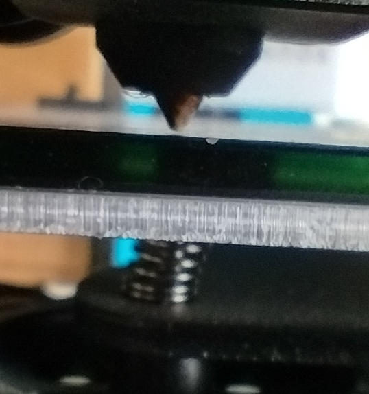
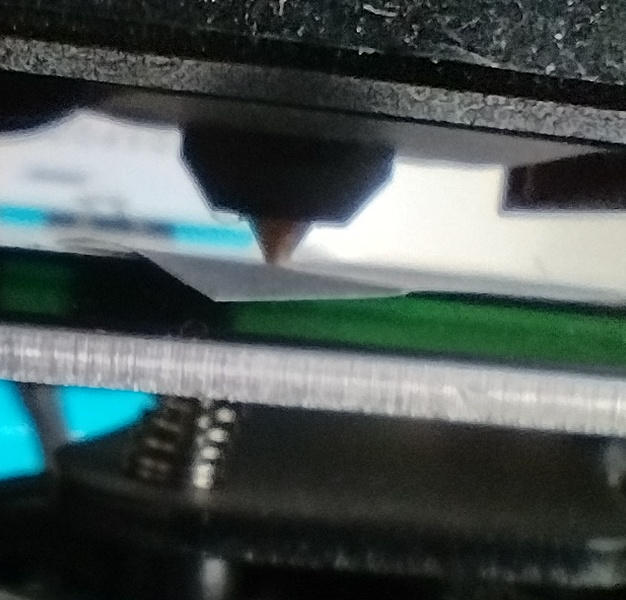
When leveling the bed on an Ender 3 you use four wheels that tighten down spring loaded threads that control the height of the bed. On in each corner. You need to adjust the bed not only to be level it but so that the clearance from the home position of the nozzle to the bed is vertically about 1/2 the diameter of the nozzle outlet.

On a typical set-up for an Ender 3 the nozzle diameter is 0.4mm so you are looking for a clearance between the bed surface and the end of the nozzle of about 0.2mm. Usually for a nozzle diameter of 0.4mm the layer height of each layer of the print is about 3/4 the nozzle diameter or, about 0.3mm.

The usual way to determine typical layer height is to divide the nozzle diameter by 1.25 which gives us about 0.32mm for the ideal layer height for a 0.4mm nozzle.

So my starting height is perhaps slightly under the standard layer height. The result (imho) is that the first layer extrusion gets bedded firmly down onto the bed and you are less lightly to get the print detaching from the bed during the print.

Ender 3 Leveling the Bed from Scratch.

First of all I remove the bed (either resin or glass) and then home the print head. The print head locates off the build plate (see this post) and does this by first raising the print head about a centimeter above the build plate to ensure it clears any bed material. For obvious reasons make sure there is nothing on the build plate that will get in the way of the print head.

The first thing I do after homing the head is re-mount the bed and then get the bed down/up to a sensible height. An example of when you need to do some serious movement this is if you change the bed to/from a glass bed from a resin bed. A resin bed is much thinner than a glass bed so you’ll need to wind the thing up/down as appropriate. But if its just re-leveling the same bed then it won’t be far off.

Secure the bed. Whether you plan to use tape, book spines (see this post) or spring clips, at this point, I’d just use spring clips and then replace them later on if you want to.

Disable the steppers. (on the control panel go to “Prepare” then click on “Disable Steppers”). This allows you to freely move the bed under the nozzle. Obviously wind the wheels so that the nozzle is clear of it. Make sure that the nozzle then can move all over the bed without touching it at any point.

Now we need to individually adjust each wheel so to bring the nozzle to within 0.2mm of the bed.

To get the height right the easiest way is to use a strip of standard 80gsm photocopier paper. Cut a strip about 2.5cms/1 inch wide. Standard 80gsm photocopier paper is about 0.1mm thick. So wind the bed so that the paper is not snagged but is <just> beginning to snag. Just so much that you can still slide the paper under the nozzle but it feels like it is beginning to catch on both the bed and print head.

Now with the paper still under the nozzle and held in place so it moves with the print head, I move the print head by hand across the bed and then move the bed back and fore while checking every few centimeters that the paper is not too loose or snagged completely. Adjust the wheels in turn until you get the same feeling from the paper all over the bed. Go over it twice just to check.

You will need to level the bed after every print although hopefully you should find (assuming the print has come off the bed without too much difficulty) the bed height stays pretty much in the right place after the initial set-up. But don’t take it as a given! Check it before you print again. Maybe though if you haven’t changed the bed type then you can just skip removing it before auto-homing.

Ender 3 Leveling the Bed: Self Leveling kits

If all that seems a bit of a faff and you have a few dollars/Pounds/Euros to spare then you can buy a self leveling kit.

Basically there are two.

The first self leveling kit was the BL Touch. This works fine with 8 bit boards and (I assume) 32 bit as well. You can find an example of a BL Kit on Amazon here.

If you have a 32 bit motherboards in your Ender 3 then you can use a CR Touch. Although CR Touch is more sophisticated than the BL Touch, it will NOT work with an 8 bit motherboard. See this post. You can check-out a CR Touch Kit from a reputable seller on Amazon on this link.

Currently I use neither. That is not because I don’t see their value. They both have amazing write ups. But as things stand I can live with the nausea of manual bed leveling. For the time being at least. But maybe in the future I’ll buckle down spend a few dollars/pounds. Then I ca stop wasting my time leveling the bed by eye!

How to Change Filament on Ender 3

This is just an aid-memoire regarding how to change filament on a Creality Ender 3 3D printer.

Changing/reloading the filament is pretty straightforward. But I know from personal experience that there are a couple of minor snags/irritants that can occur due to “economies” in the design of the Ender 3. Though it has to be said that for the money the Ender 3 is really good value. The latest version (far better than mine!) is here on Amazon.

Removing Existing filament.

Assuming the filament has not snapped in the Bowden tube then removing it is easy. Turn on the Ender 3 go to “Prepare” on the display then scroll down to either pre-heat PLA or pre-heat ABS. Select the one that is appropriate. (see more later in the post if you are using something a little more exotic like TPU). Then select “Preheat PLA/ABS End” There is no need to heat the bed up.

The pre-heat PLA on my machine raised the print head temperature to 190 degrees centigrade whereas the pre-heat ABS raises it to 240 degrees centigrade.

Opening the spring clip when you change filament on Ender 3
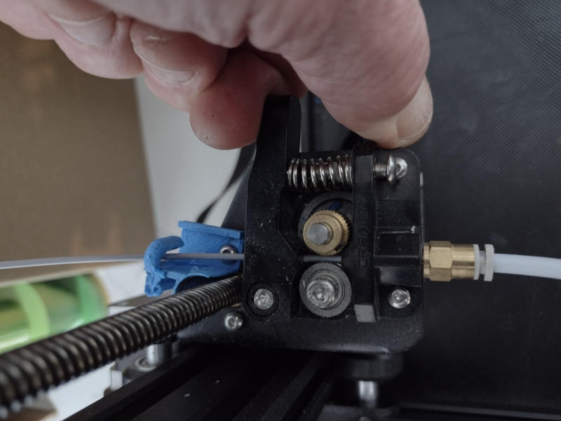
Pinch the feed head assembley spring clip to withdraw the filament

When the print head reaches temperature the filament can simply be pulled out. You need to pinch the spring clip on the entry feed to the Bowden tube so to release the pressure on the filament. Then with the other hand pull out the filament.

That’s it! This will obviously leave a small amount of filament in the print head. If you are going to use the same type of filament then imho the best thing to do is feed it in now. Use it to “push out” the last of the old batch. Which brings us to the first of my irritants with the Ender 3.


Feeding in new filament.

In an ideal world all you have to do is remove the old roll of filament from the hanger, put the new roll on it then push the filament in through the nozzle entry, through the spring clip, down the Bowden tube and into the print head.

But for me that rarely happens. The spring clip on the entry to the Bowden tube misaligns the filament and I (personally) have a devil of a job getting the damn thing into the Bowden tube. It is one of those jobs that needs three hands.

  • One to operate the spring clip
  • One to push the filament through
  • One (with a blade/spatula or whatever) to line the filament up with the entry to the Bowden tube so it goes in.

Sometimes I find that even when you get this far the filament then fouls on the entry to the Bowden tube!

My work round for not having three hands goes something like this.

I remove the Bowden tube from the feeder motor assembly. I do this by pushing the white ring in and then simply pull it out.

Then from the reverse side I feed in a small length (say 6 inches long) of filament and into the grip of the spring clip. Then I feed the new filament in. I try and snag it against the short piece so the short piece “leads” the new filament in through the entry hole to the Bowden tube.

I suppose you could try hitting it with a soldering iron to join the two together or whatever, but I find that usually with a couple of attempts the short length successfully leads the new filament into the Bowden tube aperture.

When it’s through, I feed it into the Bowden tube and re-insert the Bowden tube into the feeder motor assembly. Then it is just a matter of holding open the spring clip pushing the filament down the Bowden tube into the print head. Keep pushing gently and the new filament will melt and expel the old. You can watch the color change as it comes out. There will only be a few inches of waste.

How to Change the filament type on Ender 3

What if you want to change filament on an Ender 3 from one type to another. Say you wanted to go from using PLA to ABS or vice sa versa. Then there’s two ways to do it. (I’ve done both, but I now prefer the first option which is to change the nozzle).

The first is to change the extruder nozzle for a new one. Or of course, you can change it to one that has previously been used with the new type of filament you are loading. (See this post on how to change nozzle) Nozzles are cheap (see Amazon here) so this really is not going to break the bank if you need to fit a new nozzle when you change material.

But alternatively you can also simply feed in the new filament and displace the old. The only caveat with this is that obviously the filament in the print head has to be molten enough to get pushed out by the new stuff coming in.

If the original filament was ABS (molten from around 220 degC upwards) and you are pushing in PLA, heating the bed to 190 degC (That’s the Ender 3 setting for pre-heating the print head for PLA) is probably not going to get the remaining ABS up to a high enough temperature to allow the PLA to push it out.

But luckily there is a sweet spot where both ABS and PLA are molten. It’s around 220 degC.

So instead of using the “Prepare”→Preheat facility, go to “Control”→Temperature→nozzle. Wind the print head temperature up to around 220 degC.

When it get up to around there try gently pushing the PLA in and see if the ABS comes out. If it doesn’t then you can up the temperature a little and try again. Or of course, you can always just change the print head. Going the other way (i.e adding new ABS to a print head previously used with PLA) is less fraught as the PLA will be well molten at ABS pre-heat temperature (240 degC). Just use the same method.

Other filament types generally have temperature ranges very similar to PLA so they are less prone to difficulty. Assuming you are feeding them into replace PLA or vice sa versa.

Filament Types and Temperatures.

Here’s a list of rough working temperatures for a range of filament materials I’ve picked up off various places on the internet. Hopefully they are correct but caveat emptor!

3D printing Filament Operating Temperatures

  • PLA 200 – 230 degrees Centrigrade
  • ABS 230 – 270 degrees Centrigrade
  • TPU 205 – 300 degrees Centrigrade
  • PETG 220 – 250 degrees Centrigrade
  • PLA+ 210 – 235 degrees Centrigrade

These filament types all have different niches. But in many cases they also overlap for general use. I feel it is worth having a selection rather than just staying with PLA. Here’s the SunLU page on Amazon that gives a brief description of each filament type. Another Amazon supplier with a good range of both types and colors is Duramic 3D on this link.

Filaments generally tend to start going “runny” about 10 degrees below their minimum working temperature. So if you are pushing one out with another choose a temperature sweet spot that suits both.

But what if the Filament snapped in Bowden Tube?

So how do you change the filament on an Ender 3 when the filament has somehow broken in the filament tube? So that after pulling it out you leave a few inches in the tube at the bottom which blocks it?

You have to detach the Bowden tube at the extruder. Push the white ring in and hold it in. Then withdraw the Bowden tube with the other hand. Withdraw the Bowden tube from over the filament. Then when the filament is exposed simply pull it out of the hot print head.

There is a (BIG) warning attached to doing this. Make ABSOLUTELY SURE that when you refit the Bowden tube that it goes right back in as far as it can go. If you leave any space between the Bowden tube and the rear face of the extruder nozzle you seriously risk getting a blockage when you are half way through your next print. Any bit of debris in the print head <may> prevent the Bowden tube fully entering the chamber and butting up to the nozzle.

Personally I’d take the nozzle out and push the Bowden tube right through. This will flush any such debris out (see this post for how and why). But I suppose as long as you are sure that the Bowden tube really has gone all the way back in then you can wing it. If your Bowden tube gets frayed/damaged it is easily and cheaply replaced one example is this link on Amazon Two meters for $7.99 !! That should keep you going for about twenty years!

Anyway, writing up how to change the filament on an Ender 3 has turned out to be a long post. Much longer than I intended frist! But I hope it helps.

Ender 3: Changing the Nozzle.

On an Ender 3, changing the nozzle is easy. But it is also all too easy to foul up the filament feed by mis-aligning the nozzle to the Bowden PTFE tube channeling the filament into the nozzle. Here’s an earlier post on exactly this problem and what happens.

Why change the Ender 3 Nozzle?

If a nozzle in an Ender 3 that is only ever is used with (say) PLA and is never accidentally grounded on the build plate then it may last for years. But one grounding may (but not always) distort the exit hole and you may end up with a rough print.

At the end of the day nozzles are cheap. (here’s a good example on Amazon) You can buy better ones (like this on Amazon) but personally I stick with the cheap and expendable. If you have a suspicion that your print quality is suffering due to some nozzle abnormality then the best, cheapest (in both time and reduced print failures) and most productive fix is to change the nozzle.

The other reason people may wish to change the nozzle is when you change filament type from (say) PLA to ABS or TPU. Although you can flush the nozzle out in situ (I usually do) it may be easier to just change the nozzle for a new one. If you keep the swapped out nozzle (and label it!) you can of course re-fit when you want to go back to using the original filament type.

Some folk recommend that you change the nozzle every 3 months anyway. That’s irrespective of whether the print quality is degrading. But personally I only ever change it (sometimes) when swapping filament type. Or of course, when it get damaged by wear and tear.

Ender 3: Changing the Nozzle: Possible Problems.

Swapping the nozzle on an Ender 3 is straight forward and short of doing something catastrophic like cross threading it, risk free. But there is one gotcha (and… it got me! See this post) involving the mating of the nozzle to the end of the Bowden (white PTFE) feeding the filament into the print head. But more in a minute. Lets remove the existing nozzle first.

Removing the Ender 3 Nozzle.

When you received you shiny new Creality Ender 3 you should have found a number of cheap (but effective) tools bundled in with it. Included in this kit are two small spanners. One of these is a fit for the nozzle. There are also 3 hexagonal Allen keys one of which you will need to undo the two silver screws holding the fan unit on the side of the print head. Find your tools!

Remove the Filament

First of all remove the filament. The easiest way to do this is to turn on the Ender 3, select “control→temperaure→nozzle” and set it to your filament melting temperature (example 205 deg C for PLA) then go back to the info screen and wait until it is up to temperature. Pull the filament right out of the Bowden (PTFE) tube from the feed as it goes into the stepper motor. Then go back to control→temperature→nozzle and set it back to zero. Make sure you have moved the print head up the Z axis (prepare→move axis→z) so you can actually get at it easily with the bed getting in the way. Turn off the Ender 3.

Fitting the new Ender 3 Nozzle

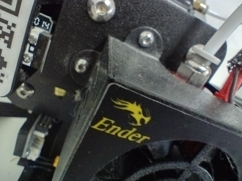
remove these two small screws

With the correct sized Allen key undo the two screws holding the fan unit onto the side of the print head. Remove the fan unit. There is no need to disconnect anything electrical. Just (obviously) don’t have the Ender 3 turned on!


Gently pull off the rubber shield.

ender 3 print head rubber shield
The rubber shield around the nozzle

Notice when you take off the rubber shield how the nozzle meets up with it with just the tip poking though. It is rubber and it will tear if you are not careful. Be gentle.Do not forget to refit the rubber shield at the end!


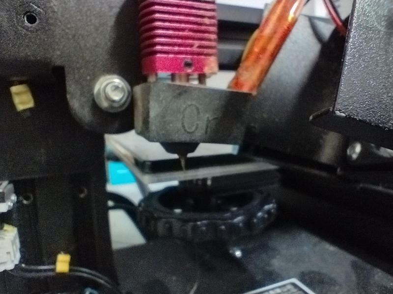
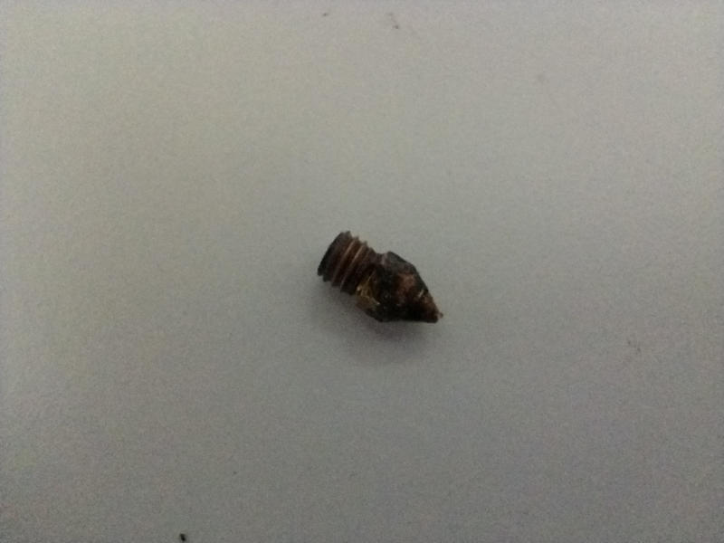
A well used ender 3 nozzle. Often PLA can “cake” around it making it difficult to get the spanner on to remove.

Now we are ready to start changing the nozzle on our Ender 3. Using the correct size spanner undo the nozzle. DON’T forget you are working upside down! So when you place the spanner on the nozzle with the spanner handle to the left you need to push it forward NOT pull it back. Doing that will simply tighten it further. Just be gentle with it. It’ll come out fine.


Ensure the Bowden tube path is clear

Watch out! This is very, very, very important!

Push the Bowden tube through the print head until it comes out the bottom.

If you just fit another print nozzle you may well not meet the end of the Bowden (PTFE) tube flush. So first of all push the Bowden tube right down through the print head so you can see it coming out of the body of the print head where the nozzle will go. If it won’t go then you’ve probably got some debris in the pathway (old glob of filament or whatever). Gently but firmly keep pushing. It will come though. Then check that the end of the Bowden tube is OK. You can of course completely remove the Bowden tube to check it but it is still very important that you clear out any debris in the print head that might prevent the Bowden tube mating up cleanly to the end of the new nozzle.

At the end of the day the Bowden tube MUST fit flush and true to the nozzle end. Otherwise there will be grief and suffering.

Hold down the collar on the Bowden tube and pull it back up so you can screw in the nozzle. Screw in the nozzle.Be aware that some/most of the thread will still be showing. And do not over tighten it. Be aware it does not screw in that far when the print head is cold. On mine I reckon it’s about 1 and half turns in total. To get the nozzle properly into the heating element, you need to turn it on and re-heat the head to working temperature (say) 200 degC). Then you will find the nozzle will easily screw into the head. Just watch you don’t burn your fingers! Use a spanner! When its in then back it off half a turn.

Push the Bowden tube back down in again. Be SURE it has gone down to the nozzle. I.e as far as possible. Lock the Bowden tube in place with the collar at the top of the print head. Then finally go back to the nozzle and tighten it in that last half turn you backed off earlier.

Refit the rubber boot then refit the fan, and you are ready to reload the filament!

If you don’t get that Bowden tube to mate cleanly with the end of the nozzle you will have a void in between them. The hot filament will deform (corkscrew) into it and block the nozzle. But, only after a while. So you start off printing nicely then it all goes horribly wrong as the filament blocks. So make absolutely sure the Bowden tube butts up to the end of nozzle.

There is a great video on YouTube (Here) that goes through more-or-less the same process as this. If you are still unclear I’d recommend you watch it. (incidentally, I don’t know the guy. Neither am I an affiliate or whatever of his – it’s just simply great information).

A very good video describing the Ender 3 print head

Ender 3 Glass Bed.

Heavily used Ender 3 Glass bed
Here’s my Creality glass bed mounted using just two spring clips. It’s in need of a clean!

I was lucky enough when I bought my Ender 3 to get a Creality branded glass bed thrown in with the deal. Actually I think that this was really a sweetener due to the fact my Ender 3 has the old 8 bit processor running Marlin 1.1.x software not the new all singing and dancing Marlin 2.x supporting 32 bit processor.

Frankly though, I’ve not missed the 32 bit software upgrade (though that may be because I don’t have it!) For what I use the printer for, it has never been an issue being limited to Marlin 1.1.x. I don’t expect many other people would find it that limiting either. But obviously some would. You can though easily upgrade to 32 bit if you so wish. Here’s one advertised on Amazon here with several hundred 5 star ratings.

But I would not want to go without my Ender 3 Glass bed. While I’ve used the resin bed that also came with the purchase (mainly to see what it was like), I’ve found the glass bed much easier to use and particularly to clean! (here’s one for less than $20 on Amazon)

The Ender 3 glass bed is for obvious reasons much heavier and thicker than the resin bed, but even when poorly/weakly secured I have never (yet) had it move on me. Neither have I ever had a problem with bed heating.

My glass bed gets a bit of a hard life. I’ve used all sorts of different adhesives to ensure the first print layer sticks. I’ve used Pritt Stick (standard school glue – here on Amazon if you want) , Spray Mount (re-position-able Adhesive spray – also here on Amazon) to Hair Spray (I’ll leave you to find that one!). They all seem to work OK.

Currently I’m using (on the Glass bed at least) re-positional Spray mount. It’s quick clean and effective and it gives a really good adhesion. Maybe though it is a little too good in fact. It it tends to bake on. But after printing I’ve always been able to knock the print off the glass bed. It takes some elbow grease to clean it off the glass but I’ve found that it does come off eventually. But I wouldn’t use it on the resin bed (again anyway!). You can see below that the adhesion is perhaps a little too good and it has been a devil to clean the resin bed without damaging it.

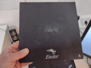
Ender 3 resin bed is more difficult to clean than the glass bed.
Here’s my resin bed after using Spray mount to adhere the first layer of a print – that refuses to come off. It looks like I’m now damaging the plate so I’ll live with it as it is.

I’ve found that cleaning the glass bed especially when used with Pritt stick is a doddle. I take it off the Ender 3 and then using soap and water, or even cream cleaner. It comes up like new. Even using a mildly abrasive scouring pad has not damaged it. Whereas my attempts to clean the resin bed (as you can see) has been less successful. I don’t think I’ll try and get the remains off this resin bed. As I appear to be now damaging it. I definitely won’t be using spray mount as the first layer adhesive on the resin bed again either!

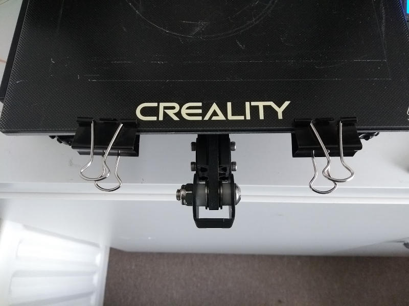
I’ve secured the glass bed to the build plate using the standard spring clips. Two appear to be fine. I’ve also used cut-down book bindings (see this post) . I’ve also simply taped it down with sellotape. All have worked. But the sellotape went a bit gooey due to the heated bed.

If you don’t have one, I’d recommend you get a glass bed. If though you are looking for a self leveling system be warned the CR Touch is incompatibe with the 8 bit Ender 3’s. More in this post.

CR Touch: Ender 3 Processor issues

I received a comment on an earlier post on this subject (here) by Matt who has an Ender 3 1.1.5 Silent motherboard. It appears that this board is incompatible with the (relatively) new CR Touch self leveling system. I’ll go more into processor identification below but this is what I’ve gleaned about the CR Touch self leveling kit. I hasten to add this is just what I’ve found out. I believe it is correct but I don’t have a CR Touch system myself.


The reason for Matts incompatibility is that it looks like the CR Touch is only compatible with 32 bit processor boards NOT 8 bit boards on the Ender 3. Most adverts for the CR Touch make this unclear or bury it in the small print. That’s if they mention it at all!. So people could easily spend the money and end up with something that simply won’t work with their system.

Here on the left is an Amazon advert that actually DOES clearly state that you need a 32 bit board. There are many other advertisers (for exactly the same kit) that leave this very salient fact out. Or at least obscure it.

If you have an 8 bit Ender 3 system and (like me) are happy with it as-is yet you want a self leveling kit then there is this earlier BL Touch kit also from Amazon (Here). Personally I still struggle along with a Mark One eyeball and a piece of paper (more in another post!). But I can appreciate that many would rather short cut the nausea associated with leveling the bed, spend a few Dollars and buy the kit.

Anyway. More on processor issues and identification

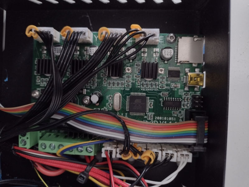
I’ve done two other posts on this subject here and here. So this is really just further explanation on what they already say. But here’s some more images and explanation. Basically if you are unhappy relying on the USB connector type as the identifier then you will need to open up the Ender 3 processor box. It’s only three screws. Then carefully lift off the cover (watch you don’t snag the fan) and have a look.

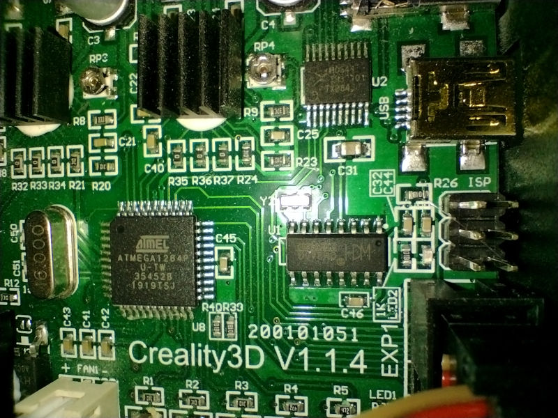
At the bottom of the street cred pile for an Ender 3 is the old 1.1.4 Atmel 8 bit processor board (like mine). Here she is in all her glory. Next is a close-up of the processor. The USB connector is a mini USB.

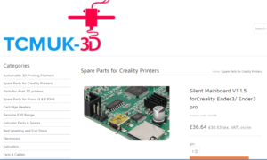
TCMUK still sell the 8 bit “Silent” board for the Ender 3

Then there is the 8 bit 1.1.5 “Silent” Atmel board. From this site I took this screenshot of the USB connector on the left. So it looks very much like the 8 bit 1.1.5 board also has a mini USB connector. Just like the earlier 1.1.4 board.

To directly address Matts issue regarding 8/32 status of a 1.1.5 board there is this Amazon advert that, though rather poorly worded, advertises an upgrade to a 32 bit board from the 8 bit “Silent board”. with pictures of both.

(As of the 27th Nov 22 the above advert is “out of stock” It looks like actually getting hold of a 1.1.5 board anywhere else as well is no longer possible. If for some reason you wanted one then I think you will be out of luck. So, in my humble opinion the best solution is to go straight to a v4.2.7 board like this one on Amazon. Looks like they are also about half the price the old 1.1.5 boards used to be too!)

Notice the difference between the two boards in the second image down in Amazon page. Although you can’t see it properly, (on the right hand side of each) notice the USB connector and the different foot-print. I.e I’d suggest that the 8 bit 1.1.5 board has a mini USB. While the 32 bit board has a micro USB.

If you are keen to utilize the CR Touch system (and I hear it is very good!) then it looks like you will need to upgrade to a 32 bit board like this one on Amazon. That’s if you haven’t done so already.

Hope that helps.

Chalkie.

Creality Ender 3 Nozzle keeps Clogging: Fix

I had a really bad two days with my Creality Ender 3 where the print would start OK but would after a while (say 10-30 minutes) the nozzle kept clogging so the filament would stop feeding. The drive wheel would be doing its best and trying (but failing) to feed the filament. The nozzle was blocked. So nothing would be coming out.

Here’s a typical fouled up print:

First layer of fouled up print – It got most of the way there!

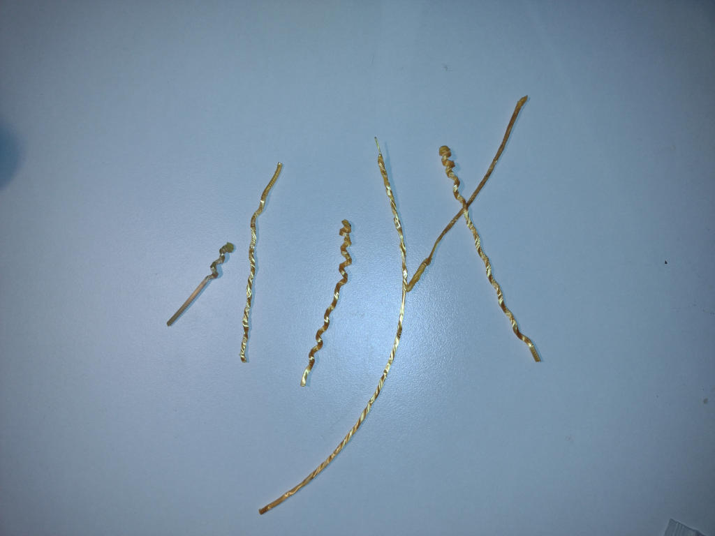
Worse still, when I tried to figure out why, and reheated the filament to get it out of the nozzle I managed to pull out nightmare contortions like these. These were all variously stuck in the hot end and I only managed to get them out by reheating the hot end on each occasion, removing the PTFE tube and pulling (hard!).

This is a gold colored PLA filament. You can see how distorted it has become from being rammed into the print head with nowhere to go.

Nozzle Cleaning Did Not Help.

I variously tried cleaning the nozzle, then changing the nozzle. All to no effect. Incorrectly I began to suspect that there was something amiss with the filament I was using. In desperation changed both the bed temperature and the nozzle. At the higher nozzle temperature the thing at least got to the end of the print, though the output was ugly and obviously too hot.

I was at my wits end. Then I Googled it and came up first with this video from Creality, which largely answered my query. But the second video is even better.

Here’s the Creality video on Nozzle Clogging first:

The Creality Video which tipped me off that the problem was with the PTFE tube

If you remove the nozzle you should be able to push the PTFE tube right through the hot end. I began to get suspicious, so I wondered, when the nozzle is actually thee, how far into the hot end should the PTFE tube go?

The Definitive Video on Nozzle Clogging in a Creality Ender 3

Then I came across this magnificent video (below) by a guy called Nerys who made a large print head model to show what the problem was. (Both videos are worth a watch but this guy’s video is awesome).

This Guys video is so clear! He gives a brilliant description of the problem and exactly how to fix it blow by blow. He is a born teacher.

The end of my PTFE tube was worn and so it mated poorly with the back face on the print head (I have a suspicion it was even worse than this! I simply had not pushed the PTFE tube in far enough!).

One thing in particular that Nerys flags up is that the top entry grommet for the PTFE into the print head should NOT be fully tightened down until the PTFE tube has been installed. The last turn/half turn will tighten the PTFE tube snugly down onto the face of the nozzle.

After all that grief and suffering, I carefully cut a centimeter off the end of the PTFE tube (make sure it is a right-angle!). Then I fFitted it back as described by the Guy in the video. I tried again with saner temperature settings. I sighed with relief when it printed perfectly.

Ender 3 – Getting the 3D Extrusion to stick to the bed – Fix

This is one of those problems for me that comes and goes for no apparent reason. But sometimes I get really bad issues getting the 3D extrusion to stick to the bed. When it goes wrong the result is usually catastrophe.

Now (I think) I have a super-cheap and reliable method to get bed adherence. I (mostly) use a glass bed.

In the past I have used (with varying success) these methods:

  • Standard Pritt-stick type glues sticks. I applied it to the bed then levelled the lumps and bumps off with a warm damp cloth.
  • Hairspray. I have only used this occasionally with limited success. Usually when I was having bad problem getting adherence with Pritt stick style glues.
  • Thinned UhU type (cellulose) glue. This type of glue is now actually quite hard to come by. It does seem to work. But it is an absolute **** to clean off the plate. Arguably it is too good at adherence. You can damage the finished item just getting it off the plate.
So here is how I get a 3D Extrusion to stick to the bed now.

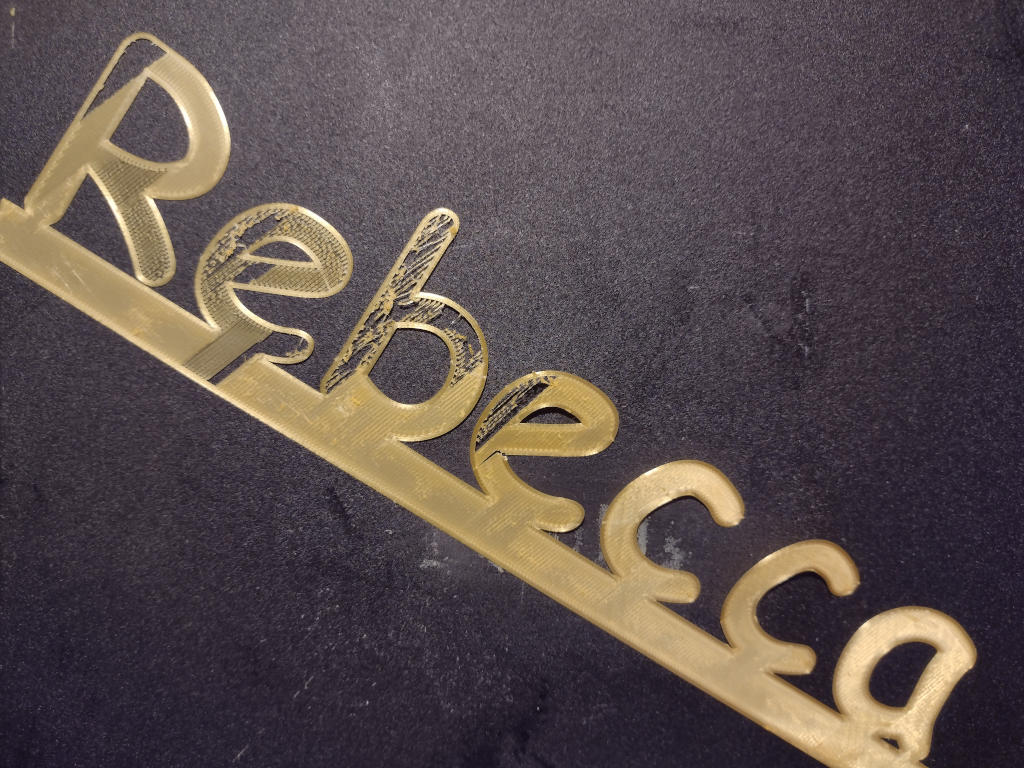
Just yesterday I was having a catastrophe. I was printing some name-tags for children of family & friends for the Xmas tree. These are, by their nature small size quite dainty. Dainty designs and getting the resultant 3D extrusion to stick to the bed really do appear to be mutually exclusive!

I’d reached to point where the only apparent way forward was to try something else. I thought about painting the glass plate I use. But with what? And for each print?

I thought about going down the road and buying some painters masking tape (I’d read somewhere that that worked).

Then (in mad inventor mode) I thought:

“If painters tape works – why not just plain paper?”

After-all plain A4 printer paper gets plastic (aka Lazer printer toner) to stick to it, so why not PLA?

I simply sellotaped a single (cut-down) piece of copier paper over the bed.

It worked first time, and every time after that. So far I have had no bad prints using it! ( except for one where I hadn’t levelled the bed properly – i.e. my cock-up).

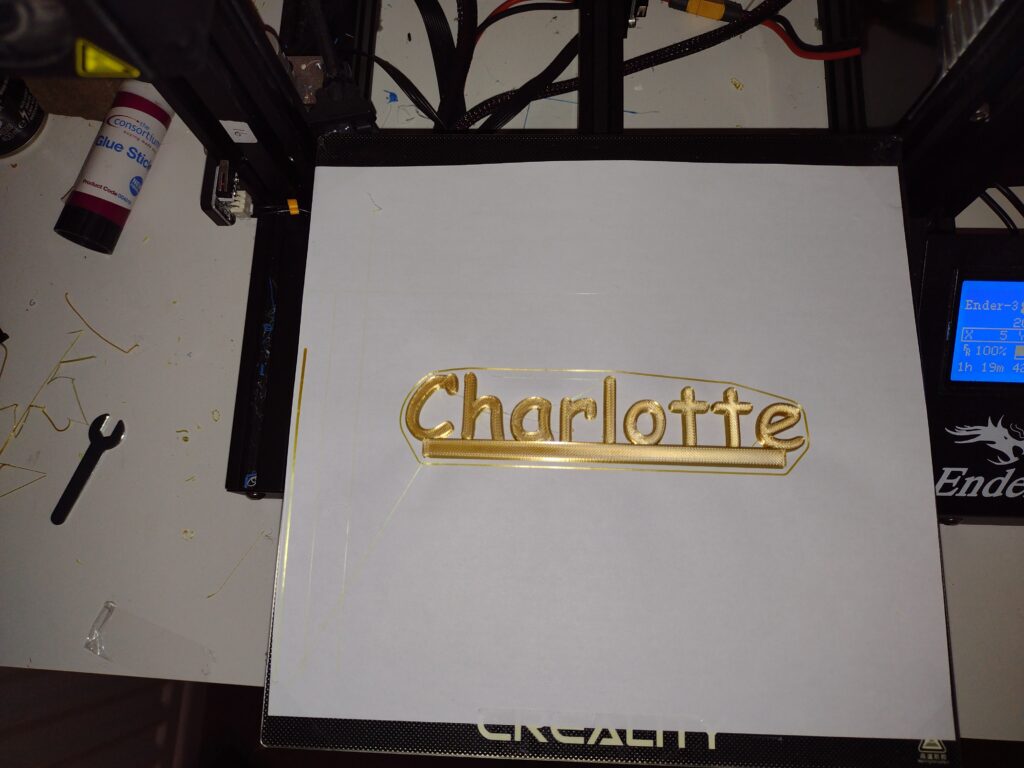
Here’s my trusty Ender-3 Paper’d up printing (this time) a large name label. I’ve taken another photo below showing the size name labels that were causing me such grief.

Simply sellotape down a single piece of printer/copier paper over the bed. Works like a Charm!

The prints, especially the bigger ones do stick really well to the paper, to the point you have to cute away the paper from the print, but if you want to get rid of the paper “base” left on the print then soak it off!

Simple!

Hope it helps.

Using paper for bed adherence
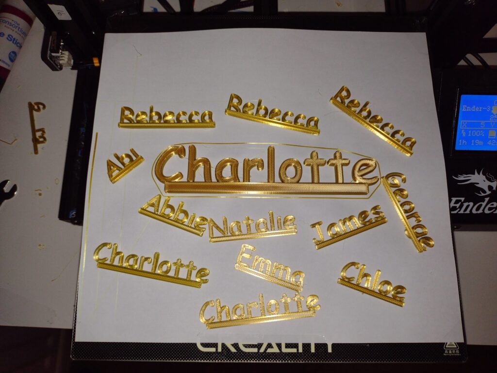
Here’s the ones I did earlier along with the bigger one. Many more to do!

The rest of my posts on 3D printing can be found on This Link

FreeCAD Snap Package Font Problems: Fix

I recently went over to using Ubuntu 20.04 from 18.04 and my new FreeCAD installation is now a snap package rather than an installation built using the traditional apt-get install route. I’ve done this for no particular reason other than that is the way thing seem to be going and frankly I just went with the flow. I wanted to get the thing working rather than fuss over how it was installed. But I ran into some Snap package font problems.

I’d used the FreeCAD snap package for a couple of small test projects and all seemed well. Then I decided I needed to make some Christmas lettering on my Trusty Creality Ender 3. To do this all I needed to do was use the ShapeString tool to get the letters from a font on my system. I’ve done this before on Ubuntu 18.04 with a traditionally installed FreeCAD package (See this post). But on Ubuntu 20.04 I hit a road block associated with the FreeCAD snap package.

One of the purposes of the snap packaging format is to limit access to system files. I assume it’s for security reasons and also so the package is not dependent upon a particular system file. This means (as well as enhanced security) that a snap package for Ubuntu should work without issue on any other flavour of Linux as well. That’s the theory anyway.

One problem with this is that Ubuntu/Linux font files are usually in either /usr/share/fonts or /usr/local/share/fonts.

So neither of these system directories are available to the FreeCAD snap package.

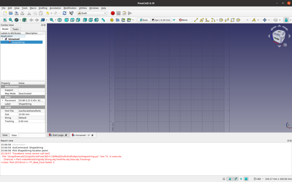
Consequently when you try and set up the path to the font of your choice in the ShapeSting tool you will find that the only directories that are available (the rest are greyed out) are those under your home directory. So, in essence you cannot set up the path to the font! While you can actually manually type in the path into the ShapeString tool, when you hit enter you get this:

Screen capture of FreeCAD ShapeScreen font problem setting error
Notice I’ve set the path to /usr/share/fonts. It doesn’t like it!
ShapreString Font problem dialog FreeCAD
Here’s what it actually says at the bottom of the above screen. Yours may be different.

So, how do you access fonts for the ShapeString tool? Well, this below works for me, but I’d be quite happy for anyone to show me a better way.

Basically you have to make the fonts you want to use available from within the bits of the file system that the snap package can see, i.e. anywhere under the user home directory. I’d suggest that it’s best not to copy them directly into the snap package location as you will probably be updating the package sometime and the fonts will be lost if you do that. Instead create (if you don’t have one already) a dot fonts directory (i.e. /home/<user-name>/.fonts) and then copy them in there.

Example:

cd ~
cp -r /usr/share/fonts/msttcorefonts/ ~/.fonts/

So far so good.

Now, go to the FreeCAD snap setup and go to directory:

/home/<user-name>/snap/freecad/current/

In here make soft link to the new fonts directory

ln -s ~/.fonts fonts

Restart FreeCAD

Then when you come to setting up the path to the font of your choice in the ShapeString tool you can now select from anything you have copied into /home/<user-name>/.fonts via the link you have in the freecad setup.

i.e example: either:

/home<user-name>/snap/freecad/current/fonts/mstcorefonts/Comic_Sans_MS_Bold.ttf (or whatever)

or by the other route that the dialog box reveals which is to the current active package version (in my case that is version 22)

/home/<user-name>/snap/freecad/22/fonts/msttcorefonts/Comic_Sans_MS_Bold.ttf

Both of these (actually the same thing!) can be selected using the dialog box associated with setting the font which is triggered by clicking on the three dots next to the font path text box.

After doing the setup you can actually set a default font for the ShapeString tool too. So if you only ever (or mostly) use one font you can set it to that. Otherwise the font path in the ShapeString tool will be blank and need setting up everytime you use it.

Do this by first selecting Draft mode first. If you don’t do this first you won’t be able to set the path for the ShapeString default font.

Now go edit->preferences. You should see a dialog box with “Draft” as the last entry on the left. Click it.

Then select the “Text and Dimensions” tab

Then in the displayed window at the bottom set the Shapestring path to your default font using the three dot navigation tool at the end of the line.

That’s it. Now when you start the ShapeString tool it will load the default font, but you can still replace with another if you want.

I have to say I’m not entirely happy with this as a solution, but it works for me. I hope (failing finding a better solution) it works for you too. If you know a better way to deal with these snap package font problems, I’d love to know what they are.

NOTE: Evidently there is/was a similar problem with the LibreOffice snap, so these Snap package font problems are not just confined to FreeCAD. A suggestion (relating to the LibreOffice problems) was that before copying the fonts to the ~/.fonts directory you run:

sudo fc-cache -fv

This refreshes the cached fonts.

I don’t think that is necessary. Although I doubt if it will do any harm.

Ender 3 Filament Spool Holder Improvement

I love my Ender 3 but one thing I found quite sub-optimal was the lack of an appropriately sized spindle bobbin for the supplied spool holder. The result is the filament hangs off centre. The larger the diameter of the internal hole of the filament reel, the worse the problem is.

To me it looked like what was needed was a spindle adapter (or bobbin) which would make the spindle sit (more or less) at the centre of the reel. This would mean the filament tension would only have to cope with a radial load. Without the spindle adapter the feed motor has to in effect “lift” the reel to spool off more. Which leads to extra tension and potentially filament tangles as the filament “digs” into the pile on the reel instead of unreeling.

Continue reading

Printing Bigger on an Ender 3

I’ve found that printing bigger on an Ender 3 than the maximum advertised print area of 220x220mm. It is fiddly but straight-forward. But there are a couple of gotcha’s that need addressing. The on-line how-to’s I have read on maximising the print area on an Ender 3 don’t seem to address them.

First of all, my Ender 3 is an old 8 bit machine running 1.1.6.2 release software. This is what it came with. I have found that with my machine there is no need to change the code in order to get the printer to print out-side the 220×220 envelope. This may not be true for everyone (see here) but it’s worth giving this a go first to save the hassle of a code change. I have used nothing exotic except a standard Creality glass bed and don’t use spring clips to hold it on. Instead I use cut down book binders as described in this post

A simple outsize Print Test

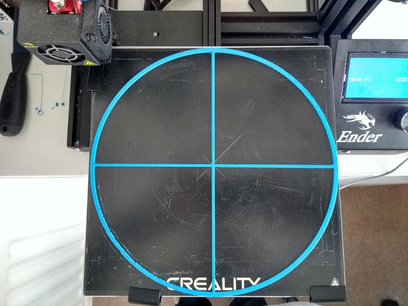
To test out printing bigger on an Ender 3 I threw together a simple circular target in Freecad. I have managed to print a circular target with a diameter of 233mm. Why not 235mm? The Creality glass bed I use has slightly rounded edges. If you try with less that about 1.0mm the print lips off the edge.

Ender 3 Using the full bed area
A simple circular target printed on my Ender 3 using the full bed area. Also notice the 5mm strip of exposed steel bed at the back. The target is actually displaced (set-up error) 1 mm to the right.
Offsets

The biggest Gotcha is the fact that the “home” position of the print head (on my machine anyway) is actually off the bed by about 1,5,0.

If you were to print at 0,0,0 (without adjusting the home offset position) then you would print into thin air.

Of course the usual remedy for this is to move the print head to the corner of bed and then set that as the home offset position. This is easy to do and is explained in this post Here.

Normally this is a perfectly acceptable solution for almost all print jobs. But not if you want to use the maximum area of the bed.

The main problem is the 5mm offset in the y direction. By zero adjusting to the bed corner as you normally you lose 5mm of the maximum bed travel (you also lose the 1mm in the x direction too) so you are straight-away limited to 230mm y direction travel (or 227mm if you account for the rounded edges and a smidgeon of tolerance)

The only simple solution that I have is move the glass bed. So instead of moving the print head to the corner of the glass bed you move the corner of the glass bed to the printhead. (don’t forget to change the zero position to equal the home position of the parked extruder head!)

Not a pretty solution I know.

You end up with the glass bed overhanging the front edge of the steel base plate by ~5mm in the y direction and ~1mm in the x direction. However I would argue that this level of overhang is not going to screw up the bed heating. For a glass bed anyway – it has a relatively large thermal capacity and so takes longer to cool.

Outsize Printing: Gcode Skirts and Brims

The other gotcha’s relate to building the Gcode. First of all, my favourite slicer – Prusa-Slic3r with it’s in-built profile for the Ender 3 won’t allow you to slice anything bigger than 220x220mm if you are using the Ender 3 profile. I would image that this can be changed but rather than risk mucking up my prized Prusa-Slic3r, I simply used Slic3r.

Obviously (or maybe not obviously) you have to turn off the brim and skirt settings. If you don’t then they are the items that dictate the maximum area in which you can print. They have to be accommodated on the print bed and they are larger than the enclosed model.

This has a couple of ramifications. The extruder does not get to extrude until it literally starts printing the job, which is not a good idea. So it would be wise to figure out adding some gcode to slic3r to get a little test extrusion done in a spare area before starting the print. I didn’t bother. But then, I was only printing targets to see what size I could print.

So that’s a simple way to get printing bigger on an Ender 3. I hope that helps.

Ender 3: Is it an 8 bit or 32 Bit Motherboard? (more on how to tell)

Creality updated the stock motherboard in their Ender 3 3d printer towards the end of 2020. So how do you tell if it’s an 8 bit or 32 Bit Motherboard? There is nothing external to the 3D printer that allows the user to figure out whether they have an older 8 bit Atmel board or a new 32 bit Arm board with the exception of of one thing. Creality took the opportunity to change the USB connector from a mini USB socket to a Micro USB socket on their stock board. I blogged about this HERE I think that this is still the easiest way to find out. But here’s some more information on identifying the boards. And… if this is not enough there more Here in a further post related to the CR Touch Self Leveling kit.

Continue reading

Ender 3: Attaching Glass Bed without Spring Clips.

My Ender 3 came with a glass bed and spring clips as well as the more usual composite bed. I like the glass bed and generally get (what I regard as) good results from it. I’ve hardly ever used the composite bed. But the thing I really hate with the Ender 3 is attaching the glass bed with spring clips to hold the bed in place.

Creality Ender 3 attaching glass bed with Spring Clips
Two spring clips at the front and two at the back. Ugh!
Continue reading

Ender 3: My Auto Home is off the plate. Here’s Why.

Creality 4.3 Inch Touch Screen Kit, Full Color for Ender-3 V2
(Click image for Amazon link)

Auto home on a Creality Ender 3 (and presumably all other 3D printers) moves the bed and the extrusion nozzle into a default “zero” position. In essence the bed and the extrusion nozzle are moved so they hit the end stop microswitches which signal to the controller board where the bed and nozzle are.

Mostly people assume that this is 0,0,0. In fact that is what it is set to in the factory defaults for the Ender 3. But if you look at the bed of an Ender 3 after it has been auto homed you will find that the nozzle is actually off the bed by about 5mm. It is not in the bottom left hand corner of the plate as you would expect.

Continue reading

FreeCad: Angled Text on a sloping surface

3D printed keyfob
The final freshly printed keyfob with raised text at an angle

This is just a simple little Freecad project to design and build a keyfob with angled text like the one below. In this previous post I detailed how to cut text into a flat object. This does the reverse. It raises text out of an object. Just to make it a little more interesting this is done on a sloping face. I skim over some parts in this. If you get stuck try this post series that describes these skimmed topics in more detail.

Open FreeCad and change the Start screen to the Part Design Screen by selecting from the dialog box in the middle of the top bar. Then click on start body and finally click on start sketch.

Continue reading

Freecad Font Path Set-up for Text String Shapes.

When you add a text string to a 3D project (like this simple one) you have to fully specify the path to the font you are using. Which is a pain and is error prone. But there is a Freecad font path set-up in “preferences”. You can specify the base directory of all the fonts. This considerably simplifies the selection. Or you can even just set one font in “preferences” and just use that with no further selection needed. But there’s a small gotcha that tripped me up for a while.

Continue reading

Printing on Creality Ender 3 with Pronterface USB connection.

This is the last part of a small series (starts here) tracking the design and processing of an ultra simple 3D project using Freecad and Prusa Slicer. Together they produced a Gcode file. This can be printed as usual using a SD Ram card. But this post is mainly about printing on a Creality Ender 3 using Pronterface (also called Printrun) on a USB connection.

Continue reading

Using Prusa Slicer to produce Gcode for a Creality Ender 3.

This is the third post in a series plotting the development of an ultra-simple plate from design in Freecad, processing the STL file using Prusa Slicer through to printing on a Creality Ender 3 3D printer. The first post in the series is HERE. In the previous post (Here) we produced a project of our 3D plate with two holes. Now we need to export it from Freecad as an STL file we can process it using Slic3r-PU

Continue reading

A Simple worked example with Freecad, Slic3r and Pronterface.

Many people intermittently use Freecad and the other associated software tools. So when they need to get a 3D design printing they have to go back up the learning curve each time. I expect that like me they go through a phase (each time!) of re-learning what should already be known. But my/your brain has “filed” it away. Hence I thought I’d produce an ultra-simple example with Freecad to remind me of the basics. If like me you are forgetful or maybe just starting to build your own 3D prints then I hope this helps.

Continue reading