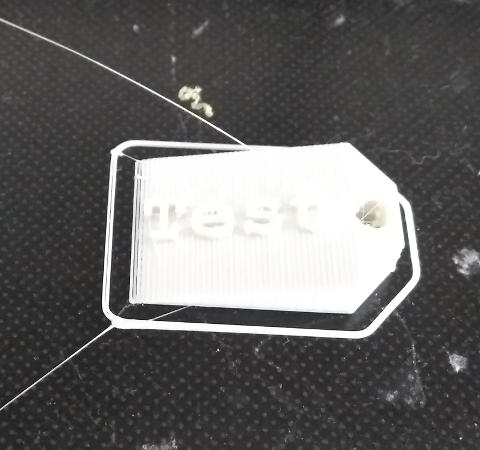
This is just a simple little Freecad project to design and build a keyfob with angled text like the one below. In this previous post I detailed how to cut text into a flat object. This does the reverse. It raises text out of an object. Just to make it a little more interesting this is done on a sloping face. I skim over some parts in this. If you get stuck try this post series that describes these skimmed topics in more detail.
Open FreeCad and change the Start screen to the Part Design Screen by selecting from the dialog box in the middle of the top bar. Then click on start body and finally click on start sketch.
Select XY plane and press OK. Now we can sketch out our key fob. Get the sketch fully constrained (see this post), click OK then you and your sketch are back in Part Design.
Extruding the basic slab
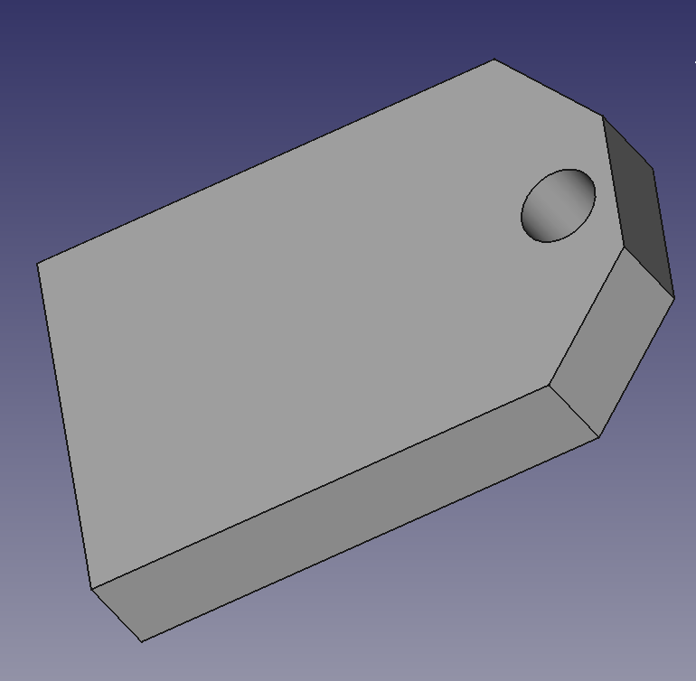
Click on extrude. Extrude it for 5mm so now we have a slab. We could if we want simply add our text here. But what fun is that?
Sketching the Slope
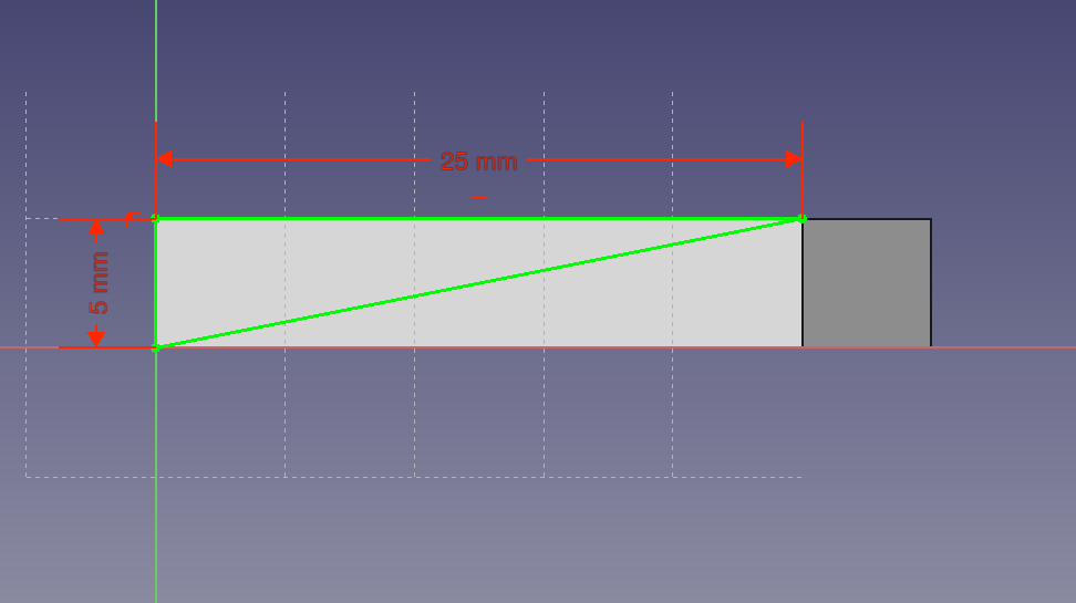
If we turn the back end of the key fob into a sloping surface we save plastic and we can then put angled text onto the sloping face. Switch the view of the key fob to edge on. Select the side face. Now select sketch. In this new sketch draw on the side of the key fob the triangle you want to cut away and constrain it like this. Click OK/Done.
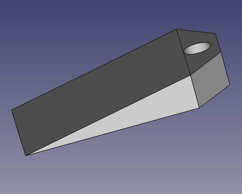
Back in Part Design click on “pocket” then select “through all”. The sketch is sliced off the key fob leaving a wedge shape. (This can be done in other ways too but this is my favourite). You end up with this:
Now position the piece so you are looking down on it. Make sure the object is flat – as if you were looking down on the text, which of course is not there yet. At this stage I usually go to wireframe mode. This allows to you see through objects and to what lies underneath.
Adding a Text String
Select Draft mode. Then select text string in shapes and build the text you want to add. A fuller description of how to add text is in this post. The only difference is that here we are extruding whereas the other post we are cutting in.
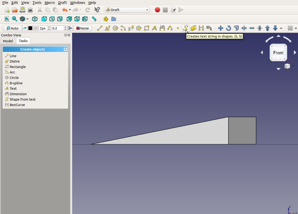
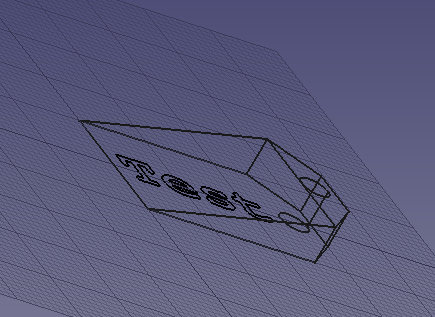
This at this stage the text is the equivalent of a sketch. So even if the above shot was in wireframe mode you wouldn’t see it. It has no thickness. If you spin it around it looks like this
Now go to Part mode (NOT Part Design) and extrude the text. You end up with text pointing straight up out of the base. It’s not angled text at this stage. Click on the Placement field and you get another box that allows you to change the angle and position of the text. This below is where I have exaggerated the angle.The green is the extruded text side on. Here it is far too tall and we’ll lower it in a while.
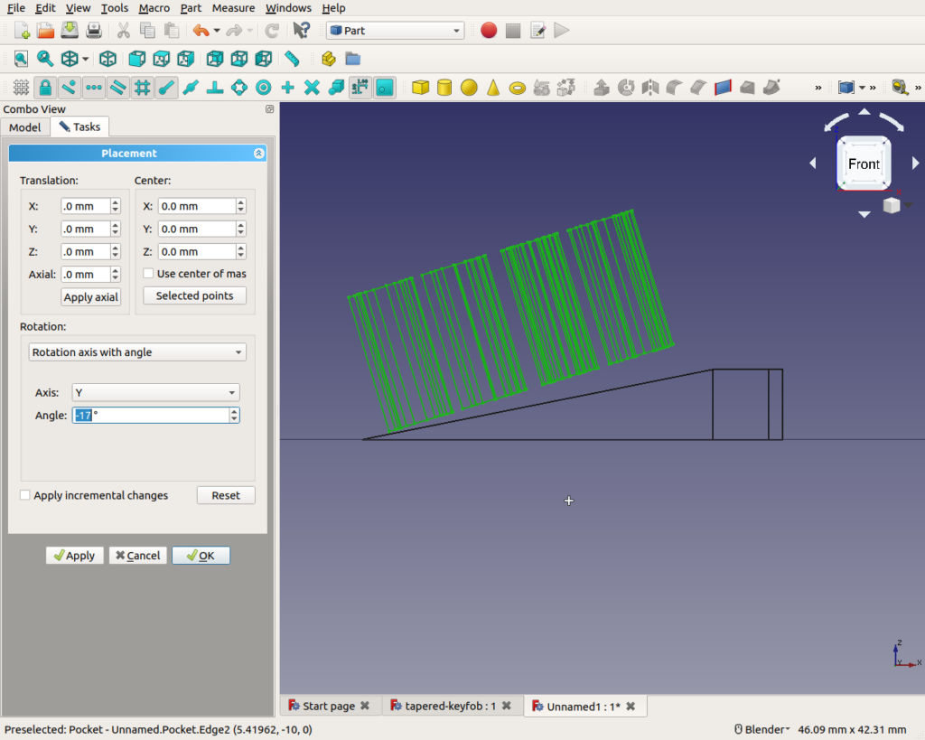
Warning: Make sure thay are fully touching
Just BE WARNED. When you are moving the text about make absolutely sure it is touching or embedded in the wedge. If it isn’t then (quite reasonably) FreeCad will not allow you to unite the text and wedge into one object.
This image above is an exaggeration. But often a tiny gap can go unnoticed. Until that is you want unite the two objects.
Get your angled text so that is at least touching all the way along. Like this:
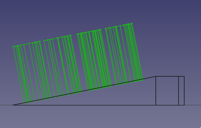
The above example has a crazily large text height so change that in the dialog when it is selected.
The final item
We end up with a 3D diagram like this:
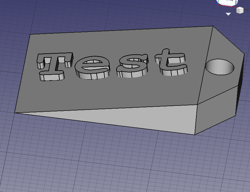
You then need to form a union of the text and the wedge. Select the objects from the left hand column. When all of the bits you want (in this case all two of them) are highlighted select menu Part->boolean->union. Then select the union that get displayed in the model field in the left hand column and export it as an STL mesh file. From there it’s over to Prusa-Slicer (see this post) and then printing.