The end result of this simple Freecad text example is a childs nameplate stencil like this one. This one was printed on a Creality Ender 3. This one needs a little clean up but you get the idea.
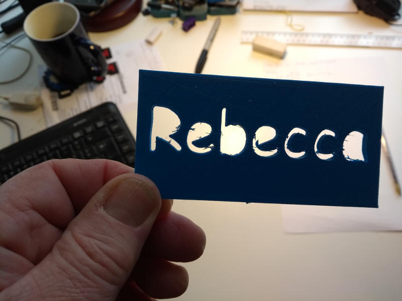
Freecad is a great tool for developing 3 dimensional drawings for 3D printing. But it is a complex tool and sometimes finding the route in to a solution can be difficult. One of the items that had me guessing for some time was how to incorporate 3D text into a design.
As a firm believer in the principle of KISS (Keep It Simple Stupid) I started out by making this really simple childs nameplate stencil. Here’s how I did it.
I’m running Ubuntu 18.043LTS but this should flow right for Windows/Mac or any other Linux flavour with minor tweaks only. Where I know what a tweak should be I’ll point it out.
I’m going to skip over making the 3D slab. If you need to know how to do this then it is exactly the same as I did in this (even simpler) example HERE. With that example just stop before you start adding the two holes and come back here.
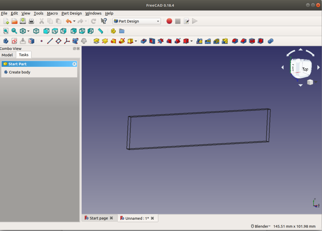
So now we have a 3D object. We could save this, export it as an STL file then use slic3r to get a g-code file and print it. But all it is is a flat slab. Totally uninteresting.
Now we need to add the text.
Keep It Flat!
In order to see what we are doing we need to go in View-Draw-style and select wireframe (you can do this by the icon short-cut too). Make sure after you have done this that view is directly from the top NOT like the in the screen capture below. Just click on “Top” on the dice in the top right corner. This will sort it out.
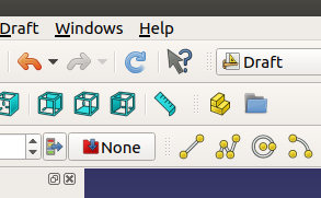
We need to back out of “Part Design” (or whatever you are in) and go into “Draft” . See top middle selector just below “Help” in the image above.
When you are in Draft mode, select the yellow S shape. This opens a dialog on the right hand side. Select the size of text, font and other parameters including font.
Fonts
YOU MUST SELECT A FONT! For example the font used in this example is at /usr/share/fonts/truetype/msttcorefonts/Comic_Sans_MS_Bold.ttf on my Ubuntu 18.04 box. You location may differ. Hunt it down. You can set the path to your fonts in Edit->”preferences” which makes accessing them much easier. Here’s how to set it up.
Click “reset point” to zero the location of the text. Press OK. If nothing much happens refresh the drawing by tapping this blue button just under Help.
The text should appear. Click on end of the placement field (three dots) in the property box of the wireframe and you’ll get this Placement dialog.
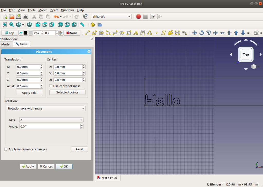
Then you can use the X & Y axes up/down arrows to move the text to the appropriate position. It does this interactively so you can watch the text move as you click. No need to guess.
At this point the text is 2D and has no depth. So go back to “Part” mode, select the extrude tool and then set the “length” (i.e. the depth) to 3mm – the same as the plate.
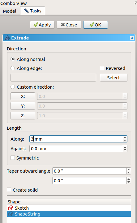
A Warning About Extrudes.
WARNING!!! Never Ever hit the “Apply” button and then “OK” as well. This will give you TWO extrudes both in the same place. The more times you hit “Apply” the more spurious extrudes you will get. Like this debacle.
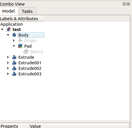
The result will be that while you cut one text string out of the block there will be another still sitting there, which will make it look like nothing has happened. If you do accidentally produce more than one extrude delete the others before continuing (right click it → delete)
Then Deselect everything. (hit Esc key a few times)
Select pad (i.e. the plate) then using ctrl-click select the shapestring extrude. Now hit the cut option.
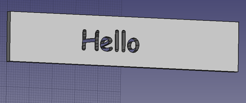
The text is “cut out” of the slab.
Change the view from wireframe to “as is” and you should see a grey slab with the text cut out of it. Like this.
Save the project and export this Freecad text example as a STL file.
To print this Freecad text example STL file we need to slice it first. See this post on how to use Pusa-Slicer to produce Gcode that actually drives the 3D printer. Then this post on how to print on a Creality Ender 3 using Ponterface to interface to it. Or (of course) copy the Gcode to an SDCard and use that.